Rachel Christensen, Abby Dunton, Darby Lyon, Paige Tilden, Natalie Mourant

Purpose
The purpose of this research was to determine if there is a significant difference in dose to the eyes of the operator when imaging anatomy of different sizes and manipulating collimation during c-arm-guided procedures.
Null hypothesis 1: There is no significant difference in dose to the lens of the eyes of the operator when imaging anatomy of different sizes during a c-arm guided procedure.
Null hypothesis 2: There is no significant difference in dose to the lens of the eyes of the operator when utilizing collimation during a c-arm guided procedure.
Background
Ionizing radiation has the potential to be harmful to the entire body, however, it is more damaging to radiosensitive tissues such as the lens of the eyes. Because of that, measures must be taken to minimize the amount of radiation emitted. For instance, collimation is an inherent feature of the c-arm that has the potential to reduce radiation exposure. However, it is only effective when manually implemented by the operator. In addition to collimation, uncontrollable factors such as tissue thickness and density also contribute to the amount of radiation received by a technologist. Therefore, the amount of scatter produced is dependent upon the body habitus of the patient and the volume of tissue exposed to the primary beam.
Materials
- University radiology lab
- C-arm
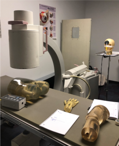
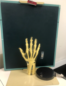
- Hand, pelvis & knee phantoms
- Keithley® Ionization chamber
- 14 x 17” CR cassette
- Leaded markers
- CR processor
- Tape
Methods
- 6 different exposures were taken, with each body part being exposed with and without collimation
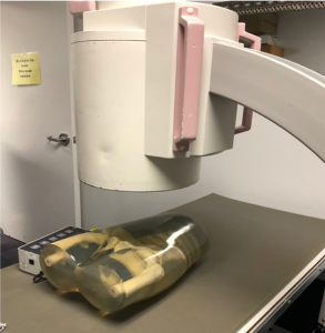
- The ionization chamber was set up 30 inches from the center of the image intensifier
- An abdominal, pelvis, and knee phantom were used to mimic real surgeries
- A CR cassette was also set up 30 inches away from the image intensifier to detect any visual scatter radiation deflecting from the phantom
- Constants & variables: the position of the c-arm, centering for each phantom, the CR cassette, ionization chamber placement and collimation
- Both quantitative and qualitative data were obtained
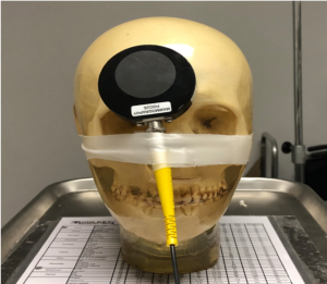
Experiment Setup
Results & Findings
- Quantitative results demonstrated less scatter radiation recorded by the ionization chamber when the field size was reduced by one-half while imaging a thoracic spine phantom.
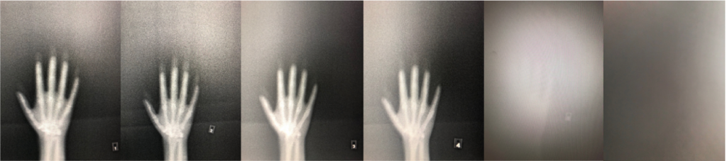
- Qualitative results demonstrated that less scatter radiation was recorded by the CR cassette when the field size was reduced by one-half.
- Both qualitative and quantitative data demonstrate that as body part thickness decreased and collimation increased, the amount of scatter radiation emitted decreased.
- Table 1 demonstrates the measured dose for the various anatomical parts in addition to the differences in collimation.
- Figure 3 demonstrates the amount of scatter radiation captured on the CR cassette for all 6 exposures.
- In most fluoroscopic procedures, the technologist is positioned farther away from the II, which suggests that minimal amounts of dose, if any, would reach the lens of their eyes.
| Exposures | Part | Does (mR) | Collimation | S# | Technique |
|---|---|---|---|---|---|
| #1 | Spine | 0.737 | None | 3327 | 70@2.6 |
| #2 | Spine | 0.434 | Iris- 1/2 the field | 6638 | 70@2.6 |
| #3 | Pelvis | 0.351 | None | 3177 | 64@2 |
| #4 | Pelvis | 0.000 | Iris | 4093 | 64@2 |
| #5 | Knee | 0.000 | None | 200 | 57@1.1 |
| #6 | Knee | 0.000 | Iris | 200 | 57@1.1 |
Limitations
- Small dosimeter chamber not used because of inaccuracy due to low-dose sensitivity.
- Large chamber placed at the head of the table rather than on the skull phantom which isn’t a realistic distance of where a technologist would stand.
- Longer exposure time of 5 seconds utilized because no dose was initially recorded.
- Due to the world-wide pandemic of COVID-19 we were not able to conduct an experiment for further research in a lab or clinical setting. All information for further research was found and cited from previous studies.
Further Research
- Further research should focus on the amount of dose received by the operator when the position of the c-arm is changed from an AP to a lateral.
- According to Carroll (2018), When in a lateral position, the amount of dose to radiosensitive tissues including the thyroid gland and the lens of the eyes increases from 120 to 600 µGy.
- With effort to minimize radiation exposure, the concept of simulated fluoroscopy was created and has proven to play a huge role in decreasing entrance skin dose (ESD) to patients by reducing beam on-time in the OR.
- Simulated fluoroscopy has many beneficial elements to improve the overall quality of patient care, all without compromising the workflow and accuracy of conventional C-arm guided procedures.
- FluoroSim compared to conventional fluoroscopy has overall reduced ESD numbers when switching from an AP to a lateral view.. “These reductions amounted to a 50% to 78% decrease in patient entrance skin dose and a 55% to 70% reduction in in-room scatter.”
- A prior experiment was conducted to demonstrate the difference in ESD and in-room scatter between fluorosimand conventional fluoroscopy. The results are displayed in Figure 6 below.
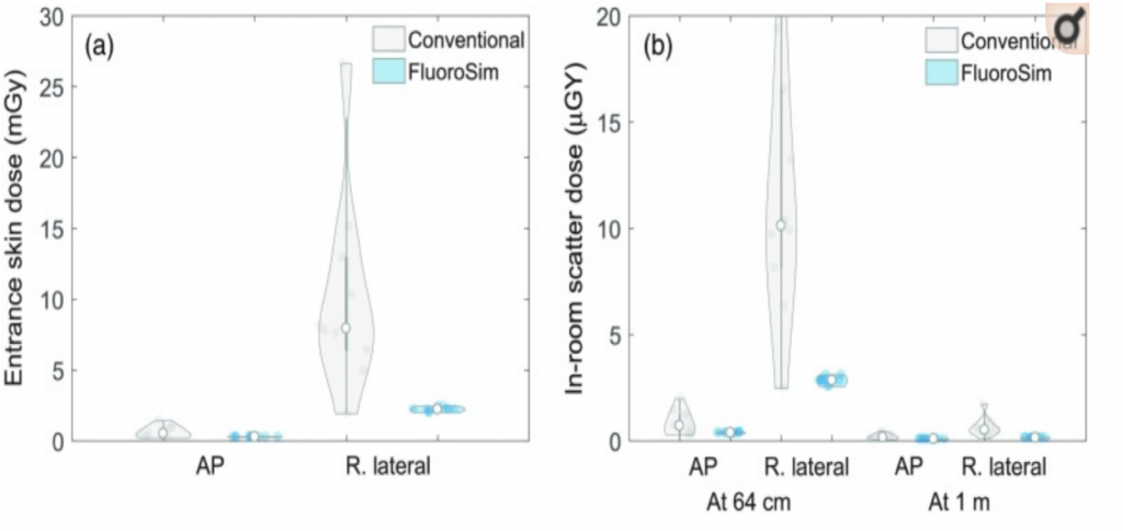
Figure 6: Demonstrates the difference in ESD between fluorosim and conventional fluoroscopy while utilizing a pelvic phantom.
References
- Baek, S. W., Ryu, J. S., Jung, C. H., Lee, J. H., Kwon, W. K., Woo, N. S., … Kim, J. H. (2013). A randomized controlled trial about the levels of radiation exposure depends on the use of collimation C-arm fluoroscopic-guided medial branch block. The Korean Journal of Pain, 26(2), 148–153. doi: 10.3344/kjp.2013.26.2.148
- Bushong, S.C. (2017). Radiologic Science for Technologists: Physics, Biology, and Protection (11th ed.). St. Louis, MO: Elsevier.
- Carroll, Q. B. (2018). Radiography in the Digital Age: Physics – Exposure – Radiation Biology (3rd ed.). Springfield, IL: Charles C. Thomas.
- De Silva, T., Punnoose, J., Uneri, A. et al (2018). Virtual fluoroscopy for intraoperative C-arm positioning and radiation dose reduction. J Med Imaging, 1(015005). 10.1117/1.JMI.5.1.015005
- International Commission of Radiological Protection. (2011). ICRP.org. Retrieved from International Commission of Radiological Protection: http://www.icrp.org/docs/ICRP%20Annual%20Report%202011.pdf
- Leyton, F., Nogueira, M. S., Gubolino, L. A., Pivetta, M. R., & Ubeda, C. (2016). Correlation between scatter radiation dose at height of operator’s eye and dose to patient for different angiographic projections. Applied Radiation and Isotopes, 117, 100–105. doi: 10.1016/j.apradiso.2016.01.013
- Suzuki, A., Matsubara, K., Chusin, T., & Sasa, Y. (2019). Eye lens doses of radiology technologists who assist patients during radiography. Radiation Protection Dosimetry, 1–7. doi: 10.1093/rpd/ncz007
- Suzuki, A., Matsubara, K., &Sasa, Y. (2017). Measurement of radiation doses to the eye lens during orthopedic surgery using a C-Arm x-ray system. Radiation Protection Dosimetry, 179(2), 189–195. doi: 10.1093/rpd/ncx250
- Uwineza, A., Kalligeraki, A. A., Hamada, N., Jarrin, M., & Quinlan, R. A. (2019). Cataractogenicload – A concept to study the contribution of ionizing radiation to accelerated aging in the eye lens. Mutation Research/Reviews in Mutation Research, 779, 68–81. doi: 10.1016/j.mrrev.2019.02.004