
Team SOKT

Not snug enough for you? This device keeps you tight all day long!

One of the most common issues that lower leg amputees have is finding the perfect fit for their prosthetic leg. Due to the amputee’s activity and diet, the volume of an amputee’s residual limb fluctuates throughout the day that distorts the fit of their prosthetic socket which leads to discomfort, pain, and sometimes even serious medical complications. A new prosthetic socket design is required which has the capabilities of sensing a change in the user’s volume around the residual limb and actively provides action to fix the situation. Using new software, our team derived a solution to allow for a socket to accommodate for this fluctuation.

Team Members

  • Garrett Auby
  • Preston Bellville
  • Clayton Lennon
  • Matthew Walsh
  • Aaron Weeks
Video Preview

Prosthetic Socket Improvements

In this video, see how test prosthetic sockets are made. Closed captions and a video transcript are available.

Smart Amputee Socket Project

Problem Statement

Amputees typically see volume fluctuations in the residual limb throughout the day that affect the fit of their prosthetic socket which leads to discomfort, pain, or serious medical complications. A new design is required which has the capabilities of sensing a change in the user’s volume around the residual limb and actively providing action to fix the situation.

Background and Problem Analysis

Volume Changes

  • Residual limb volume can fluctuate up to approximately 6% in a single day, although 3%-5% is common for most people [1].
  • From qualitative clinical observations, a “good” socket fit typically becomes an “acceptable” fit after approximately 5% volume loss or 2.5% volume gain, and becomes “unacceptable” after approximately 10% volume loss or 5% volume gain [2].
  • The ability to accurately measure and respond to these changes in volume is necessary for a successful solution. For a successful project, potential solutions must account for these volume changes throughout the day, ideally adjusting automatically

Sock Usage

prosthetic sock
  • Amputees compensate for volume change by putting on more socks throughout the day.
  • Most amputees need to add anywhere from 1 to 11 socks per day, 5 socks on average. Socks are typically added around 3 times per day to accommodate for the volume fluctuations.
  • This process of adding socks requires the user to take the prosthetic off in order to slip on the sock. The incorrect number of socks on an amputee can cause serious discomfort and even serious medical issues [3].
  • The ability to accommodate for a volume change without the use of additional socks would account for a successful design.

Stakeholder Analysis

We determined the major concerns for stakeholders to be as follows:

  • Lower Leg Amputees: Safety, Size/Shape, Comfort, Ease of Use, Uninsured Cost.
    Durability
  • Prosthetic Clinicians:  Fitment, Training, Marketing
  • Manufacturer:  Equipment Compatibility, Tools, Tolerances
  • Insurance Companies:  Insurance Cost, Validation Process

Form and Function

Control System Design

layout of control system
Control system layout

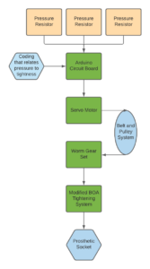
To demonstrate the functionality of the pressure sensors and motors, we will first create a control system separate from the prosthetic. The purpose of this test is to test our control system. We will fine tune the coding to create a relationship between the applied pressure and the turning of the worm gear. We will directly measure the force inside the socket exerted on the residual limb using pressure resistors. An Arduino will receive the pressure input and control a worm geared motor that adjusts the tension of the tightening cable. Worm gearing is important to prevent any backsliding of the motor.

Analysis of Performance

Modified BOA System

Flow chart for proposed control system

This design makes use of existing BOA socket tightening systems and automates the tightening process.

The design would utilize force sensing resistors located on the panel in contact with the tibia to measure the pressure on the limb. The tibia is one of three identified contact points with the existing socket. The data will be sent to an Arduino that would reside under the boa tensioner. The Arduino would interpret the data and drive a servo motor that would lead into a pulley system which drives a worm gear system to control the boa tensioner. The worm gear allows the system to be controlled in both directions to accommodate for increases or decreases in volume.

Pressure Resistor

As per the list of specification, the user sees a pressure of around 20-60kPa in order to hold the socket to their residual limb. The sensor that has been selected has bounds from 0.646-151kPa. Being well within the range that the prosthetic will see and easy to adhere to the socket itself, these resistors will be an excellent choice for data collection.

Arduino

The Arduino will be able to receive analogue input from the sensor and use it to make decisions controlling the motor.

Worm Geared Box DC Motor

The original Boa system uses a ratcheting mechanism to ensure it does not loosen during use. To achieve this same effect while also being able to tighten and loosen as necessary, a worm gear set will be used to provide one-way power transmission from the motor to the Boa. This will keep the load off of the motor when not actively tightening/loosening, as well as prevent “backsliding”. The motor selected provides 16kg-cm of torque while maintaining 12RPM.

Boa Tightening System

The Boa tightening system has been provided by Kormylo – Advanced Prosthetics and Orthotics. This device has mapped out areas that have been determined as areas of contact critical for maintaining a tight fit with the patient. The Boa system is integrated into a prosthetic socket and will be modified in order to accommodate for the added electronics.

Testing of Performance

Our concept will need to be tested to ensure both safety and functionality of the socket. Testing goals and procedures are TBD, and may include any of the following:

  1. Concept to initially be tested on non human entity such as a plastic bottle or balloon to simulate a leg.
  2. After confirming measurement feasibility on inanimate objects, an amputee volunteer will test the tightening system.
  3. Force analysis tests during walking.
  4. Gait testing to determine if the design is overly detrimental to the patient’s walking patterns
  5. Comfort testing with patients to make sure that the design is wearable throughout the day

References

  1. Sanders, J. E., Harrison, D. S., Allyn, K. J., & Myers, T. R. (2009, December). Clinical utility of in-socket residual limb volume change measurement: case study results. Retrieved from https://www.ncbi.nlm.nih.gov/pmc/articles/PMC4435543/
  2. Sanders, J. E., & Fatone, S. (2011). Residual limb volume change: systematic review of measurement and management. Journal of rehabilitation research and development, 48(8), 949–986. Retrieved from https://doi.org/10.1682/jrrd.2010.09.0189
  3. Bloomer, Gary. Prosthetic Sock Management Tool. TechLink, Retrieved from https://techlinkcenter.org/technologies/prosthetic-sock-management-tool/
  4. Montgomery, J., Vaughan, M., and Crawford, R. (July 9, 2009). “Design of an Actuated Volume Compensating SLS Prosthetic Socket.” J. Med. Devices. June 2009; 3(2): 027534.
  5. Chris. (2019, December 19). Average Vertical Jump: By Age, Sport, NBA and NFL. Retrieved from http://www.homeexerciseequipmenthq.com/average-vertical-jump/
  6. Steer, J.W., Worsley, P.R., Browne, M. et al. Predictive prosthetic socket design: part 1—population-based evaluation of transtibial prosthetic sockets by FEA-driven surrogate modelling. Biomech Model Mechanobiol (2019). Retrieved from https://doi.org/10.1007/s10237-019-01195-5
  7. APRadmin. (2014, May 20). What is the “True” Weight of Amputees? Retrieved from https://aprpros.com/true-weight-amputees/
  8. Centers for Disease Control and Prevention. (2017, May 3). FastStats – Body Measurements. Retrieved from https://www.cdc.gov/nchs/fastats/body-measurements.htm

Return to Capstone Design Showcase Home Page