A LabView Interface for Laboratory Test Equipment for the Visually Impaired
Randall Bassine and Kris Campbell
Department of Electrical and Computer Engineering
Abstract
We have developed a test and measurement module that interfaces LabView [1] software with the common undergraduate laboratory test equipment including a digital oscilloscope, waveform generator, and multimeter. The interface converts the measurement data from a monitor display to a spoken readout for a visually impaired student. This interface is flexible and can be adapted to any piece of laboratory test equipment. This poster presentation includes a demonstration of a multimeter readout of a circuit, using the student version of the Digilent Analog Discovery 2 measurement system. The future goal of this work is to adapt the interface to include all Boise State University Electrical and Computer Engineering undergraduate laboratory test equipment, and to have the interface detect and read the mouse position when it is above an input or readout area on the equipment interface screen.
Introduction
In Electrical Engineering undergraduate circuit laboratories, the standard test and measurement equipment is not user friendly for visually impaired students. In order to create an inclusive environment for visually impaired students, we have created a test and measurement system that combines LabView instrument control software [1] with the Digilent Analog Discovery 2 (AD2) hardware [2], and Windows Speech SDK 5.1 for voicing the measurement results.
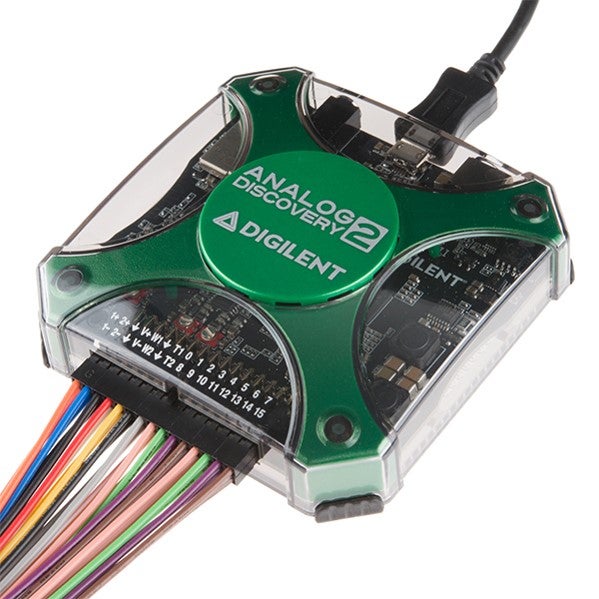
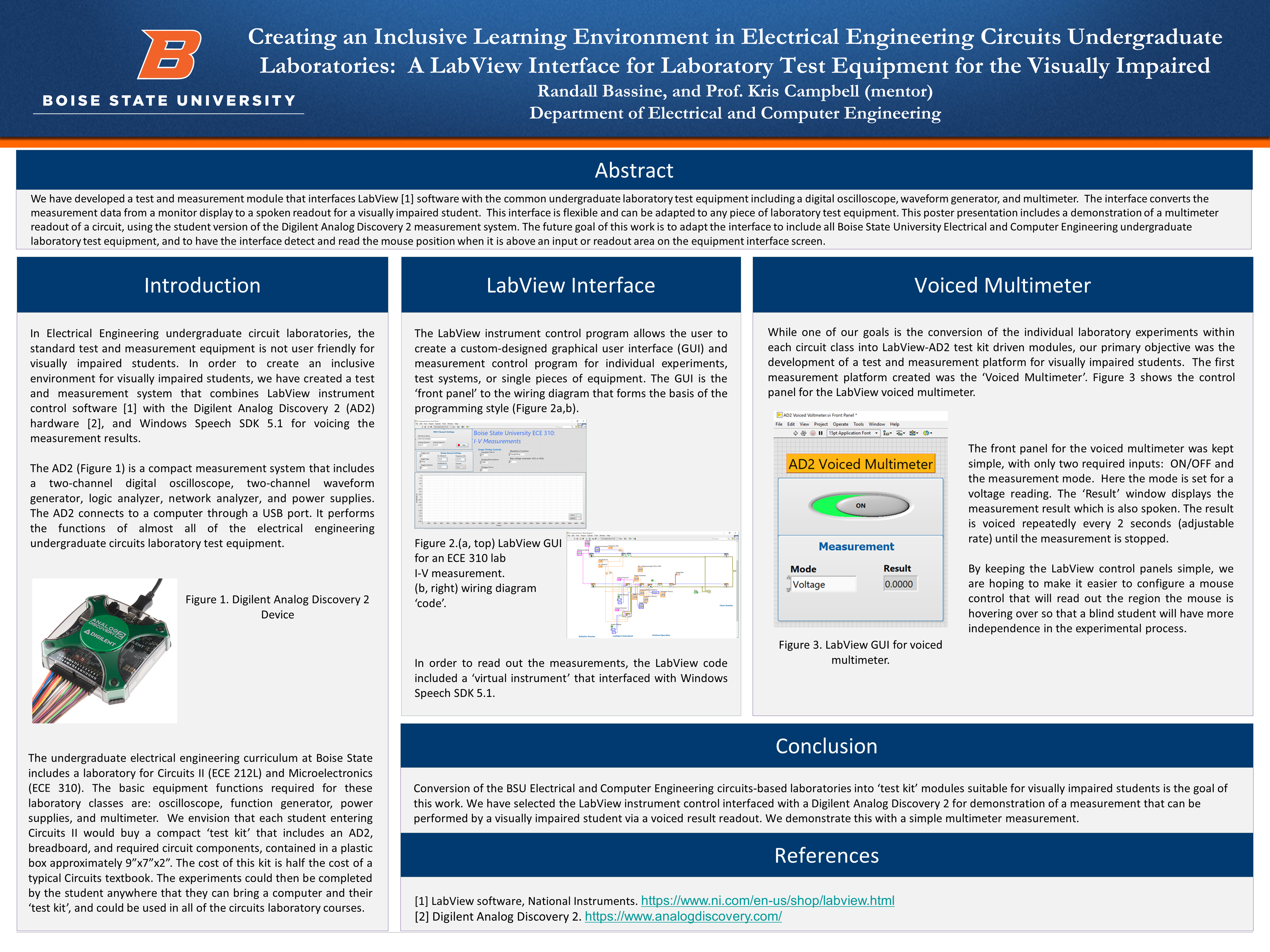
The AD2 (Figure 1) is a compact measurement system that includes a two-channel digital oscilloscope, two-channel waveform generator, logic analyzer, network analyzer, and power supplies. The AD2 connects to a computer through a USB port. It performs the functions of almost all of the electrical engineering undergraduate circuits laboratory test equipment.
The undergraduate electrical engineering curriculum at Boise State includes a laboratory for Circuits II (ECE 212L) and Microelectronics (ECE 310). The basic equipment functions required for these laboratory classes are: oscilloscope, function generator, power supplies, and multimeter. We envision that each student entering Circuits II would buy a compact ‘test kit’ that includes an AD2, breadboard, and required circuit components, contained in a plastic box approximately 9”x7”x2”. The cost of this kit is half the cost of a typical Circuits textbook. The experiments could then be completed by the student anywhere that they can bring a computer and their ‘test kit’, and could be used in all of the circuits laboratory courses.
Electrical Measurements
The LabView instrument control program allows the user to create a custom-designed graphical user interface (GUI) and measurement control program for individual experiments, test systems, or single pieces of equipment. The GUI is the ‘front panel’ to the wiring diagram that forms the basis of the programming style (Figure 2a,b).
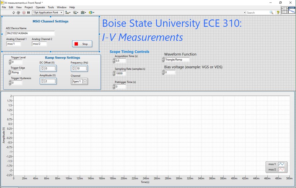
I-V measurement.
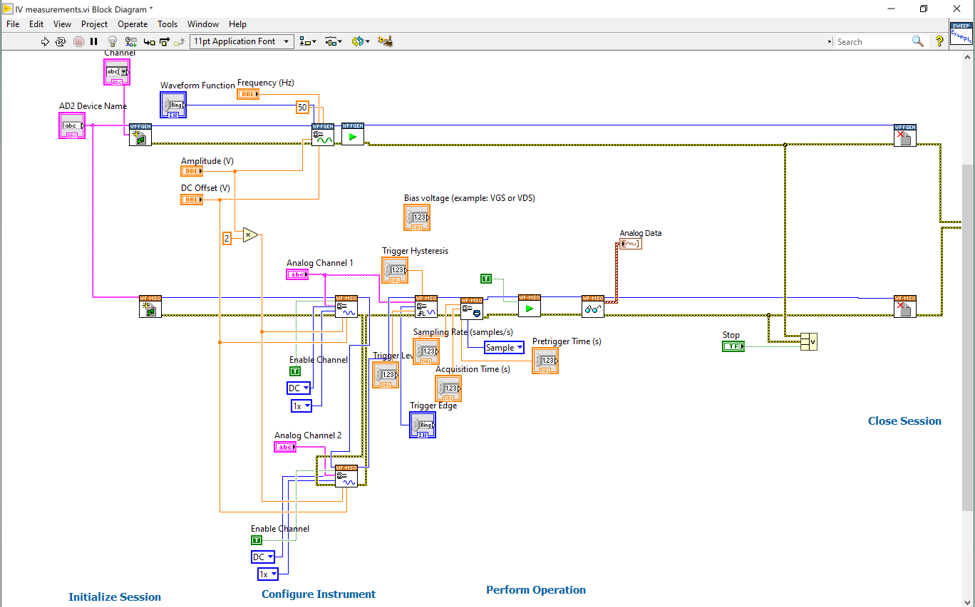
In order to read out the measurements, the LabView code included a ‘virtual instrument’ that interfaced with Windows Speech SDK 5.1.
Voiced Multimeter
While one of our goals is the conversion of the individual laboratory experiments within each circuit class into LabView-AD2 test kit driven modules, our primary objective was the development of a test and measurement platform for visually impaired students. The first measurement platform created was the ‘Voiced Multimeter’. Figure 3 shows the control panel for the LabView voiced multimeter.
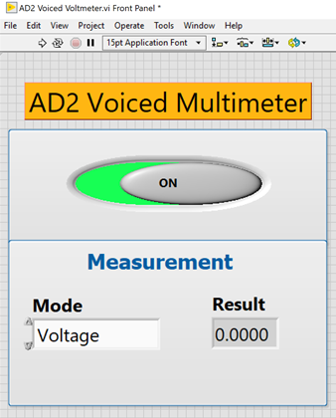
The front panel for the voiced multimeter was kept simple, with only two required inputs: ON/OFF and the measurement mode. Here the mode is set for a voltage reading. The ‘Result’ window displays the measurement result which is also spoken. The result is voiced repeatedly every 2 seconds (adjustable rate) until the measurement is stopped.
By keeping the LabView control panels simple, we are hoping to make it easier to configure a mouse control that will read out the region the mouse is hovering over so that a blind student will have more independence in the experimental process.
Conclusion
Conversion of the BSU Electrical and Computer Engineering circuits-based laboratories into ‘test kit’ modules suitable for visually impaired students is the goal of this work. We have selected the LabView instrument control interfaced with a Digilent Analog Discovery 2 for demonstration of a measurement that can be performed by a visually impaired student via a voiced result readout. We demonstrate this with a simple multimeter measurement.
References
[1] LabView software, National Instruments. https://www.ni.com/en-us/shop/labview.html
[2] Digilent Analog Discovery 2. https://www.analogdiscovery.com/
Additional Information
For questions or comments about this research, contact Randall Bassine at randallbassine@u.boisestate.edu.